In a conventional air conditioner or heat pump, engineers usually start with capacity, efficiency, operating pressure and installation constraints. Those questions still matter with R290. The added work is to map the refrigerant boundary. Because R290 is propane and is classified as an A3 refrigerant, the design must show where a leak could travel and how the equipment responds if refrigerant appears outside the intended path.[2]
For low-GWP refrigerant direction and R290 market trends, see R290 refrigerant trends in HVAC/R. This article stays with the equipment: the refrigeration cycle, HVAC architecture, likely leak paths, low-position accumulation, sensor placement and the control loop behind leak detection.
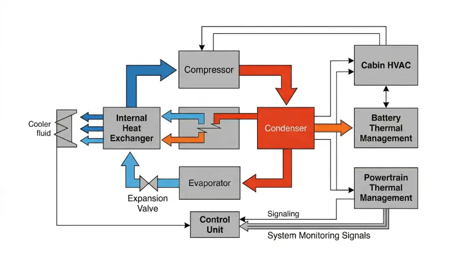
1. How a traditional HVAC refrigerant cycle works
Most air-conditioning and heat-pump systems use a vapor-compression cycle. AHRI describes the basic air-conditioning process as moving heat from indoors to outdoors through compression, condensation, expansion and evaporation.[1] The equipment is moving heat. The "cold" is the result of heat being removed from the indoor side.
1.1 Compression
Low-temperature, low-pressure refrigerant vapor returns from the evaporator to the compressor. The compressor raises pressure and temperature so the refrigerant can reject heat through the condenser.
1.2 Condensation
The hot refrigerant enters the condenser and releases heat to the surrounding air or to a secondary fluid loop. As heat is removed, the refrigerant changes from a gas toward a high-pressure liquid.
1.3 Throttling and Expansion
The liquid refrigerant passes through an electronic expansion valve, thermostatic expansion valve, capillary tube or other metering device. Its pressure and temperature drop, preparing it to absorb heat in the evaporator.
1.4 Evaporation
The low-temperature, low-pressure refrigerant absorbs heat at the evaporator and boils back into vapor. That vapor returns to the compressor and the cycle repeats.
Cycle path:Compressor -> condenser -> expansion device -> evaporator -> compressor
In heat-pump heating mode, a reversing valve changes the direction of heat transfer, so the indoor and outdoor heat exchangers effectively exchange roles. The same thermodynamic logic remains; the useful heat output is simply delivered to the opposite side.
2. In traditional split air conditioning, refrigerant often enters the building
In a conventional split air conditioner, the compressor is usually in the outdoor unit, while the indoor unit contains a refrigerant heat exchanger. Copper lines connect the outdoor and indoor units, often passing through a wall, ceiling, service shaft or equipment room. The refrigerant path may be relatively long, and the field installation process introduces joints, bends and service points.

Simplified split-system route:Outdoor compressor -> outdoor heat exchanger -> expansion device -> indoor heat exchanger -> suction line -> outdoor compressor
With non-flammable or lower-flammability refrigerants, engineers often optimize these routes for pressure drop, oil return, installation distance and service access. With R290, the same route also defines where flammable refrigerant could appear if a leak occurs in or near an occupied space.
3. R290 keeps the cycle but changes the safety boundary
R290 still follows the same vapor-compression cycle. The compressor does not become conceptually different because the working fluid is propane. The change is the design work around the refrigerant circuit.
Because R290 is an A3 refrigerant, engineers need to answer questions that are less visible in traditional split-system design:[2]
- Can the R290 refrigerant path be shortened?
- Can total refrigerant charge be reduced while maintaining performance?
- Can field joints and potential leak points be reduced?
- Can R290 be kept out of long-term occupied indoor spaces?
- If indoor routing cannot be avoided, how will risk be limited and detected?
- If a leak occurs, where will gas accumulate under running and stopped conditions?
- Can the controller trigger ventilation, shutdown or other mitigation before risk rises?
Shorter refrigerant paths are easier to verify and easier to protect.
4. Why many R290 heat pumps keep the refrigerant outdoors
One common R290 air-source heat pump architecture is the monobloc design. In this approach, the compressor, refrigerant-side heat exchangers and R290 circuit are concentrated in the outdoor unit. The building receives heat through a water loop rather than through indoor R290 refrigerant piping.

Outdoor refrigerant side:Compressor -> air-side heat exchanger -> expansion device -> water-side heat exchanger -> compressor
Indoor water side:Water-side heat exchanger -> pump -> floor heating / radiator / fan coil -> return pipe -> water-side heat exchanger
Not every R290 HVAC product must use a monobloc layout. The architecture is useful because it makes the refrigerant path clear: keep the flammable refrigerant outdoors when possible, then move energy indoors through a secondary loop.
5. R290 split systems need a new architecture review
R290 can be used in direct-expansion or split-type equipment, but the equipment needs to be designed around propane. Charge limits, pipe routing, installation rules and safety logic cannot simply be carried over from an R32 or R410A platform.
The design team must recheck compressor compatibility, heat-exchanger volume and expansion-device matching. Pipe joints also need a fresh count because every connection adds a long-term reliability point. Field installation, ignition-source management, gas dispersion and service tools belong in the product definition stage.
For an R290 split system, draw the refrigerant path first. Then place sensors, control actions and validation tests around it.
6. Where R290 leak monitoring should be placed
More sensors do not automatically make the equipment safer. Location matters more: where leaked gas appears first, where it may stay and how much time the controller has to respond. Sensor placement should be checked through equipment-level leak simulation and testing, not chosen from a single assumed leak point.

6.1 Why low-position areas matter
R290 is propane. A liquid leak can flash into vapor and spread through the equipment enclosure. A common propane SDS lists its relative vapor density at about 1.5 to 1.6, with air equal to 1.[6] When the fan is stopped, local airflow is weak or the enclosure has sheltered spaces, heavier vapor can stay low in the unit.
The bottom of the unit, base-pan recesses and areas below partitions deserve a closer look. Poorly ventilated pockets should be reviewed separately. These areas affect sensor placement, enclosure openings, drainage layout and ventilation paths.
Denser vapor does not make the lowest point the automatic sensor location.
Gas movement inside equipment is shaped by leak rate, refrigerant temperature, fan behavior and internal airflow. During operation, airflow may carry R290 away from the lowest area. After shutdown, vapor may move downward again. Practical sensor placement starts with likely leak sources, then checks those assumptions against airflow and leak-simulation results.
6.2 Compressor Compartment
The compressor compartment usually gets reviewed early. It has vibration, suction and discharge connections, oil, temperature changes and electrical parts. Leak monitoring, enclosure ventilation and ignition-source management should be planned there from the start.
6.3 Valves, Service Ports and Pipe Connections
Every joint, service port, valve body and field connection is a position that needs long-term reliability assessment. The design objective is to reduce unnecessary joints and make unavoidable connections easier to validate, inspect and protect.
6.4 Base Pan and Low Enclosure Cavities
Low-position cavities can collect leaked vapor when local airflow is weak. Review the base pan for drainage and corrosion, then check whether it creates pockets that slow gas dispersion.
6.5 Indoor Units in Direct-Expansion Designs
For specially designed R290 split systems, the indoor unit also needs review. Return-air paths, indoor heat exchangers and connection points affect how leaked gas moves. Installation height, room volume, fan state and ventilation conditions affect how quickly abnormal concentration can be recognized.
6.6 Water-Side Heat Exchanger Boundaries
In monobloc heat pumps, engineers also review the boundary between the refrigerant side and the water side. Normal operation should keep R290 outdoors. Abnormal heat-exchanger behavior, pressure changes and isolation requirements still need defined handling.
7. Reducing R290 leak risk is a system design task
Leak risk is not solved by a single component. A practical R290 design controls charge and routing, reduces unnecessary joints and plans ventilation, ignition-source control, sensor placement and controller response together.
7.1 Reduce Total Refrigerant Charge
Within performance requirements, reduce the total amount of R290 by shortening the refrigerant path, reducing unnecessary internal volume and controlling charge accurately. Charge limits and acceptable mitigation methods vary by product category, market and standard pathway.
7.2 Reduce Joints and Field Connections
Every added connection creates a location that must remain reliable for the life of the equipment. Factory-assembled, factory-charged and factory-tested sections can reduce uncertainty compared with long field-assembled refrigerant paths. This is one reason monobloc R290 heat pumps receive attention.
7.3 Manage Potential Ignition Sources
A leak does not automatically mean immediate danger. The risk appears when a flammable concentration reaches an ignition source. Relays, switches, motors and high-temperature surfaces should be assessed against where refrigerant may appear. Arcs, static discharge and overheated components matter too.
7.4 Plan the Post-Leak Ventilation Path
The equipment should avoid pockets where gas can remain trapped. Designers should review base-pan recesses, sealed spaces, baffle-created dead zones and locations where gas cannot naturally disperse. In some designs, the controller may use a detection signal to start or maintain fans or trigger other mitigation actions.
7.5 Connect the Sensor to the Control Loop
An R290 sensor works best as a controller input, not as a stand-alone alarm. Depending on the product design and applicable standard, the system may maintain ventilation, stop the compressor, manage electrical loads, report a fault or require manual reset.
A detection signal has value when the controller can use it.
8. R290 leak detection cannot be judged only by initial sensitivity
HVAC equipment may run for years through temperature changes, humidity, condensation and vibration. Field conditions may also include dust, oil contamination, cleaning agents and electrical interference. Sensor selection should look at response time, drift, environmental robustness, diagnostics, communication method, mounting method and service cost.
UL's public guidance on refrigerant detection systems describes requirements around detection method, reliability, robustness, deviation and drift over life in the context of UL 60335-2-40 refrigerant detection updates.[4] For OEMs, the practical question is whether the sensor still supports stable risk recognition after years of equipment operation.
9. How standards influence R290 HVAC design
IEC 60335-2-40 covers particular requirements for electric heat pumps, air conditioners and dehumidifiers, and is a design reference for many HVAC products.[3] In R290 projects, standards affect equipment structure, charge and installation space. They also shape leak detection, ventilation, fan behavior, control logic, fault response and whole-machine testing.
For North America, UL's materials describe updates in UL 60335-2-40 fourth edition and Annex LL for refrigerant detection systems, including detection-method and lifecycle reliability considerations.[4][5] Different markets, product types and equipment architectures do not have identical requirements. Specific thresholds, charge limits and mitigation actions should be confirmed against the applicable standard text, target market and certification body.
10. What changes when HVAC systems move to R290?
| Design Question | Common Focus in Traditional HVAC Systems | Additional R290 HVAC Safety Focus |
|---|---|---|
| Refrigerant cycle | Compression, condensation, expansion and evaporation | The basic cycle remains unchanged |
| Refrigerant route | Performance, cost and installation convenience | Shorter, more concentrated route; reduced indoor refrigerant exposure |
| System charge | Efficiency and capacity | Also affects post-leak risk boundary |
| Pipe connections | Reliability and service access | Reduce joints and field connections where possible |
| Indoor unit | Can include refrigerant heat exchanger | Requires reassessment of indoor leak scenarios |
| Enclosure | Waterproofing, dust, heat dissipation and maintenance | Also avoid gas accumulation and plan dispersion routes |
| Electrical parts | Function, EMC and reliability | Also evaluate potential ignition sources |
| Sensors | Status monitoring and alarm | Safety input in a controller-based response loop |
| Validation | Performance, durability and environmental testing | Add leak simulation and mitigation verification |
Conclusion: R290 brings the system boundary into the design work
R290 keeps the basic thermodynamic cycle intact. The change is that refrigerant piping becomes both a performance circuit and a safety path. R290 HVAC design should address charge, routing, field connections and indoor/outdoor boundaries early. Ventilation, leak monitoring and system response then need equipment-level validation.
R290 sensors cannot solve the whole problem alone. They need enclosure design, controller logic and actuators around them before they become useful parts of the safety design.
Solution:Explore R290 HVAC Leak Detection Solutions
Explore R290 HVAC Leak Detection Solutions
References
References are listed in the order they first appear. External links open in a new tab.
- AHRI, How Air Conditioning Systems Work. https://www.ahrinet.org/scholarships-education/education/homeowners/how-things-work/air-conditioning-system
- ASHRAE, ASHRAE Refrigerant Designations. https://www.ashrae.org/technical-resources/standards-and-guidelines/ashrae-refrigerant-designations
- IEC, IEC 60335-2-40:2024. https://webstore.iec.ch/en/publication/83993
- UL Solutions, Updated Requirements for Refrigerant Detection Systems. https://www.ul.com/insights/updated-requirements-refrigerant-detection-systems
- UL Solutions, Refrigerant Detection Systems. https://www.ul.com/resources/refrigerant-detection-systems
- Airgas, Propane Safety Data Sheet. https://www.airgas.com/msds/001045.pdf